Did You Know?
MGCP is a master/slave protocol that allows a call-control device (such as Cisco UCM) to control and track the state of each voice port on the gateway, and there two things you need to know about MGCP Protocol.
In case of MGCP , the Dial plan administration is done within the call manager, so all call routing decisions are done based on Cisco UCM configuration.
When Cisco Voice gateway receive call setup message from PSTN, Gateway will convert incoming TDM setup messages that contain Both Calling & Called Numbers to IP Packets and forward them to the Call manager as in our case Gateway doesn’t handle layer 3 messages, after that call manager will take the routing decisions and route the call to the appropriate destination.
Notes
The first steps in Troubleshooting MGCP GW in our systematic approach will be checking E1/T1 Connections status, and this can be done using well-known command : show isdn status and the output should look like below
DE-DUS-ENT-CE1#show isdn status
Global ISDN Switchtype = primary-net5

%Q.931 is backhauled to CCM MANAGER 0x0003 on DSL 0. Layer 3 output may not apply

ISDN Serial0/0/0:15 interface
	dsl 0, interface ISDN Switchtype = primary-net5
	L2 Protocol = Q.921 0x0000  L3 Protocol(s) = CCM MANAGER 0x0003
    Layer 1 Status:
	ACTIVE
    Layer 2 Status:
	TEI = 0, Ces = 1, SAPI = 0, State = MULTIPLE_FRAME_ESTABLISHED
    Layer 3 Status:
	0 Active Layer 3 Call(s)
    Active dsl 0 CCBs = 0
    The Free Channel Mask:  0xFFFF7FFF
    Number of L2 Discards = 2, L2 Session ID = 230
    Total Allocated ISDN CCBs = 0
from the output, we need to check two parameters which is the most important
now we verified that GW is registered to CUCM and ISDN status is up and now can start receiving calls from PSTN
first will need to enable two commands to trace incoming/outgoing call
The MGCP Gateway will send NTFY message every 15 sec (by default) as a keepalive. CUCM will acknowledge using 200 OK
DE-DUS-ENT-CE1#
Apr  9 12:59:44.566 GMT: MGCP Packet sent to 10.29.3.137:2427--->
NTFY 526602120 *@DE-DUS-ENT-CE1 MGCP 0.1
X: 0
O:
<--- Apr 9 12:59:44.590 GMT: MGCP Packet received from 10.29.3.137:2427--->
200 526602120
<---
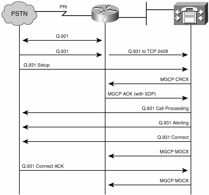
Now I am gonna make a call “Inbound ” and will go through the messages one by one, and will start with the first message ‘call setup message’ from PSTN as shown below
Apr  9 12:53:44.972 GMT: ISDN Se0/0/0:15 Q931: RX <- SETUP pd = 8  callref = 0x569C
	Sending Complete
	Bearer Capability i = 0x9090A3
		Standard = CCITT
		Transfer Capability = 3.1kHz Audio
		Transfer Mode = Circuit
		Transfer Rate = 64 kbit/s
	Channel ID i = 0xA98381
		Exclusive, Channel 1
	Progress Ind i = 0x8283 - Origination address is non-ISDN
	Calling Party Number i = 0x1180, '420547123498'
		Plan:ISDN, Type:International
	Calling Party Number i = 0x1183, '420547123498'
		Plan:ISDN, Type:International
	Called Party Number i = 0x81, '215'
		Plan:ISDN, Type:Unknown
now we received a call from PSTN Side, and if you noticed, the called Number is only 215, and this means the Provider is not sending the whole Number “DID Number”, PSTN just send the last 3 digits, and this message will be directed to CUCM to be routed to the proper extension
CUCM will send the first mgcp message here which is CReate Connection message “CRCX” to the GW, In this message the call-agent instructs the gateway to establish a connection with an endpoint, and in our case, connection supposed to taking place between GW and IP Phone, but now in this step, GW is setting up its side of the call and will be waiting for information from CUCM about the target phone in the upcoming messages
The parameters in the CReate Connection provide what is necessary to build an understanding of each connection. The parameters include the codec, packetization period, QoS marking, usage of echo cancellation, silence suppression
Apr  9 12:53:45.000 GMT: MGCP Packet received from 10.29.3.137:2427--->
CRCX 52481 S0/SU0/DS1-0/1@DE-DUS-ENT-CE1 MGCP 0.1
C: D000000003d943d4000000F58000569c
X: 1
L: p:20, a:PCMU, s:off, t:b8
M: recvonly
R: D/[0-9ABCD*#]
Q: process,loop
<---
[table id=6 /]
Till now Call manager informed the GW to send its connection parameter and the reply from GW supposed to be 200 ok with SDP
below you will see the first line for 200 ok message and GW will provide its IP address, Port Number and in our Example here GW sent its IP address: 10.22.66.185 and RTP Port Number 24488 and the Next step supposed to be informing IP Phone to send RTP Traffic to IP address and Port Number GW is using
Apr  9 12:53:45.008 GMT: MGCP Packet sent to 10.29.3.137:2427--->
200 52481 OK
I: F68

v=0
c=IN IP4 10.22.66.185
m=audio 24488 RTP/AVP 0 100
a=rtpmap:100 X-NSE/8000
a=fmtp:100 192-194
<---
[table id=7 /]
The next step now will be call proceeding Q931 message followed by Alerting message from CUCM Side toward PSTN as below
Apr  9 12:53:45.032 GMT: ISDN Se0/0/0:15 Q931: TX -> CALL_PROC pd = 8  callref = 0xD69C
	Channel ID i = 0xA98381
		Exclusive, Channel 1
Apr  9 12:53:45.032 GMT: ISDN Se0/0/0:15 Q931: TX -> ALERTING pd = 8  callref = 0xD69C
	Progress Ind i = 0x8088 - In-band info or appropriate now available
Now, since we can see Alerting message sent to PSTN, this means we are informing PSTN that we found the destination, Number is correct, it’s not busy and now it’s ringing please provide a ring back tone to the caller.
you will find also progress indicator 0x8088 In-band info or appropriate now available, to inform the PSTN that GW will provide ring back tone to the caller, and the next action will be CUCM task to inform GW to provide ringback tone to the caller
and this will be done using RQNT (Request for Notification) >> G/rt ———> Generate Ringback tone
Apr  9 12:53:45.032 GMT: MGCP Packet received from 10.29.3.137:2427--->
RQNT 52482 S0/SU0/DS1-0/1@DE-DUS-ENT-CE1 MGCP 0.1
X: 1
R: D/[0-9ABCD*#]
S: G/rt
Q: process,loop
<---
Apr  9 12:53:45.036 GMT: MGCP Packet sent to 10.29.3.137:2427--->
200 52482 OK
<---
when the IP Phone answer the call, GW will send Connect message to the PSTN and will receive connect acknowledgment from PSTN Side
Apr  9 12:53:46.016 GMT: ISDN Se0/0/0:15 Q931: TX -> CONNECT pd = 8  callref = 0xD69C
Apr  9 12:53:46.048 GMT: ISDN Se0/0/0:15 Q931: RX <- CONNECT_ACK pd = 8  callref = 0x569C
the IP Phone answer in this point of time, then CUCM will send a connect to the PSTN, and then we get connect acknowledgment coming back from the PSTN
we remember in create connection message, the GW was receiving only, as in that time GW was only setting up its side of the call, but when IP Phone answer, IP Phone will inform CUCM about RTP Port Number its using, now we can see modify connection message being sent to the GW, and in this MDCX message the critical part is adjusting this connection to send receive instead of receive only, as connection now need to be initiated between GW and IP Phone, so MDCX message will contain SDP to provide the information about IP Phone [RTP Port number + IP address] to let GW communicate with the phone and RTP Packets to flow from GW to the IP Phone
Apr  9 12:53:46.220 GMT: MGCP Packet received from 10.29.3.137:2427--->
MDCX 52483 S0/SU0/DS1-0/1@DE-DUS-ENT-CE1 MGCP 0.1
C: D000000003d943d4000000F58000569c
I: F68
X: 1
L: p:20, a:PCMU, s:off, t:b8
M: sendrecv
R: D/[0-9ABCD*#]
S:
Q: process,loop

v=0
o=- 3944 0 IN EPN S0/SU0/DS1-0/1@DE-DUS-ENT-CE1
s=Cisco SDP 0
t=0 0
m=audio 28034 RTP/AVP 0
c=IN IP4 10.163.21.16
<---
below is 200 ok response from GW for previous Modify Connection message
Apr  9 12:53:46.220 GMT: MGCP Packet sent to 10.29.3.137:2427--->
200 52483 OK
<---
Now Connections is established between IP Phone and the GW and RTP packets are flowing End to End
Now, Calling Party hung up the call, and can see this in the below disconnect message that we got from PSTN,
Apr  9 12:54:00.237 GMT: ISDN Se0/0/0:15 Q931: RX <- DISCONNECT pd = 8  callref = 0x569C
	Cause i = 0x8A90 - Normal call clearing
	Progress Ind i = 0x8288 - In-band info or appropriate now available
Now, Since the caller ended the call and as a result of that, CUCM will instruct GW to update its connection as the RTP connection is no longer there “as the Caller hung up” and we need to stop the GW from listening on Port Number that was used for that connection and stop sending RTP Traffic to IP Phone using Modify Connection message,
you will notice in the M line, now we revert back to recvonly mode again and this means, GW didn’t kill the call from its side yet “receive only mean GW still listening on port number we used in the set up during the connection ” and in that point, you might be wondering,
Why we didn’t send a Delete connection directly instead of two stages for terminating the call?
The answer is: because in some cases let’s say the User did not hang up, let’s say he pressed Hold or transfer or any other function, this means modifications might be required to the current session, maybe CUCM will direct the GW to connect to MOH Server for MOH Stream, etc.
and this is the case behind two stages for tearing down the call, first will be Modify Connection and GW will respond with 200 OK as below
Apr  9 12:54:00.265 GMT: MGCP Packet received from 10.29.3.137:2427--->
MDCX 52486 S0/SU0/DS1-0/1@DE-DUS-ENT-CE1 MGCP 0.1
C: D000000003d943d4000000F58000569c
I: F68
X: 1
M: recvonly
R: D/[0-9ABCD*#]
Q: process,loop
<--- Apr 9 12:54:00.265 GMT: MGCP Packet sent to 10.29.3.137:2427--->
200 52486 OK
<---
The last message from CUCM in our mgcp call will be DeLete Connection “DLCX”, and in this message, CUCM instructing GW to stop listening to RTP Port Number that was used during the connection to End the call and free the Bearer channel
Apr  9 12:54:00.293 GMT: MGCP Packet received from 10.29.3.137:2427--->
DLCX 52487 S0/SU0/DS1-0/1@DE-DUS-ENT-CE1 MGCP 0.1
C: D000000003d943d4000000F58000569c
I: F68
X: 1
S:
<--- Apr 9 12:54:00.313 GMT: MGCP Packet sent to 10.29.3.137:2427--->
250 52487 OK
P: PS=702, OS=112320, PR=703, OR=112480, PL=0, JI=0, LA=0
<---
If you noticed in GW acknowledgment, GW did not send 200 ok as usual, instead, it’s sending 250 ok, and this because it contains additional information related to QoS.
[table id=8 /]
and this will be followed by a Release message to the PSTN Side and receiving acknowledgment coming back from the PSTN
Apr  9 12:54:00.337 GMT: ISDN Se0/0/0:15 Q931: TX -> RELEASE pd = 8  callref = 0xD69C
Apr  9 12:54:00.357 GMT: ISDN Se0/0/0:15 Q931: RX <- RELEASE_COMP pd = 8  callref = 0x569C
Cisco UC & Contact Center engineer

Eslam Rizk
1 Comment
Essam Kaseb
Such an amazing presentation!!
KEEP GOING ON ya 7ag Islam 🙂